
Dust Collector Fabrication Best Practices for Industrial Air Quality
2026-11-03
Most dust collector problems start long before installation — on the fabrication floor. A poorly welded seam or misaligned filter housing can quietly sabotage your air quality goals. That's why getting the build right matters as much as the design. In this post, we break down the fabrication best practices that industrial facilities actually need, with insights from Fanchang Machinery. Ready to see what separates a durable dust collector from a future maintenance headache?
Material Choices That Outlast Corrosive Dust Streams
Corrosive dust streams rarely behave like a uniform abrasive. They carry hot acidic gases, fine particulates that wedge into seals, and enough moisture to trigger pitting under seemingly dry deposits. At a cement kiln discharge or a coal ash handling line, plain carbon steel chutes can develop pinholes within weeks. A more durable route starts with duplex stainless grades such as 2205 or super austenitic 904L, which balance resistance to pitting and crevice attack. Don't overlook non-metallic options either: sintered alumina tiles hold up well in dry streams, while silicon carbide ceramics handle thermal shock better when the dust carries moisture or alkaline salts.
Thickness is not a substitute for the right alloy, but local reinforcement still matters. Average corrosion rates miss the way dust swirls around elbow outer walls and baffle edges, creating local erosion rates three to five times higher than the straight runs. Adding sacrificial wear plates or using Inconel 625 weld overlay on those high-impingement zones costs far less than upgrading the entire pipeline. Another underused tactic is flow conditioning: keeping conveying velocity just above saltation reduces particle rolling and grinding along the bottom, which can double the life of the parent material before replacement becomes necessary.
Weld Seams and Leak Paths: The Hidden Air Quality Drain
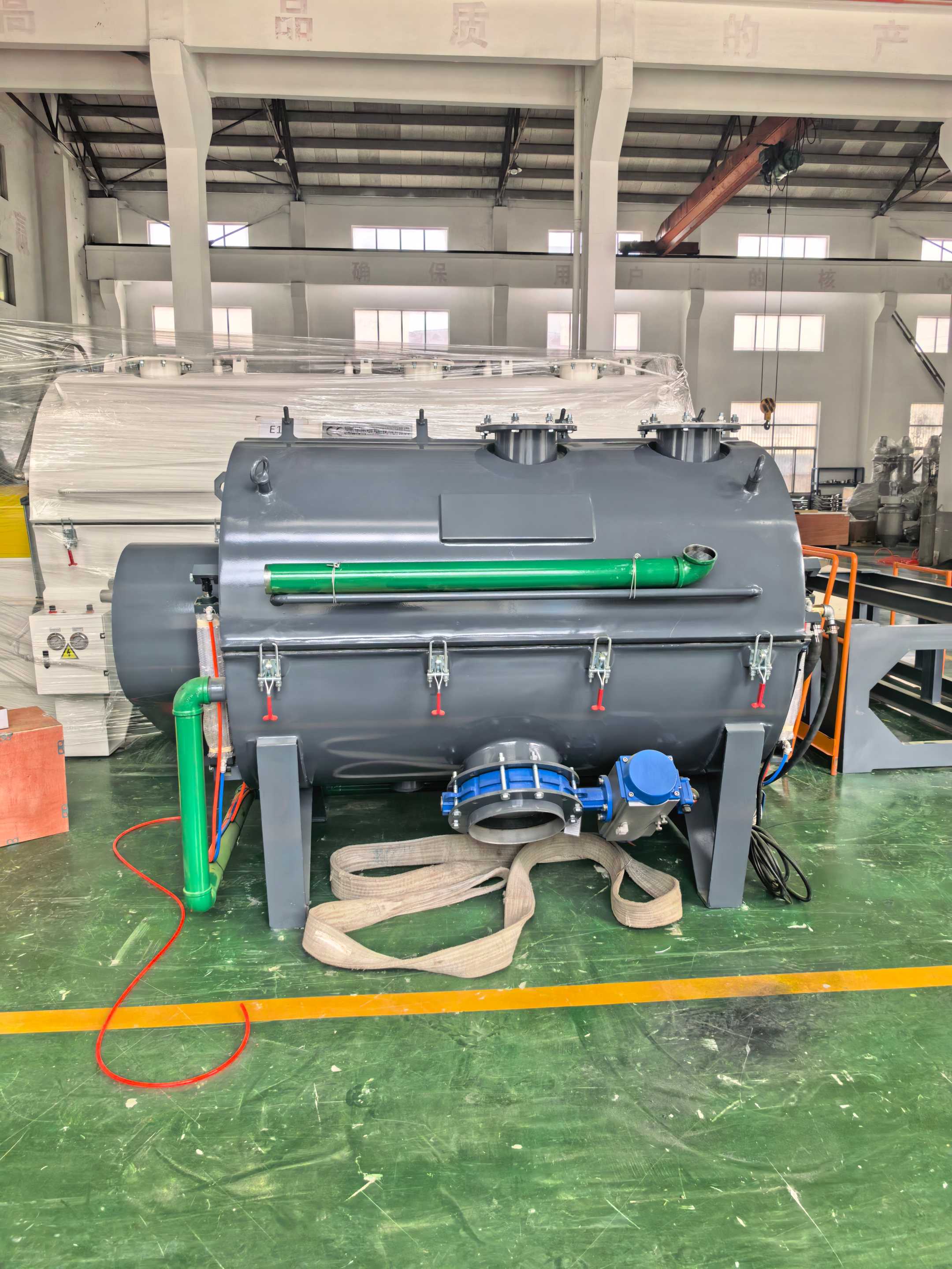
Walk past a welded joint on an air handling unit or a length of galvanized ductwork and you'll likely see nothing but smooth metal. Yet beneath that continuous bead, a network of pinholes, micro-cracks, and unwelded tack points can be breathing in ways the original design never intended. These defects aren't always dramatic enough to trigger a pressure test failure, but under the constant flex of thermal expansion and fan vibration, they open just wide enough to let untreated air slip through. The result is a quiet exchange that bypasses filters, dampers, and conditioning coils entirely.
In a building running under slight negative pressure, those same leak paths pull air from wall cavities, mechanical rooms, or even outdoors—carrying dust, insulation fibers, and whatever volatile compounds happen to be off-gassing nearby. Meanwhile, on the supply side, conditioned air escapes into unconditioned spaces before it ever reaches a diffuser, forcing the system to work harder and longer cycles. The hidden drain isn't just about energy waste; it's about the slow accumulation of particles and humidity that no sensor at the thermostat will ever flag.
What makes this problem so persistent is that traditional commissioning rarely hunts for it. A visual inspection of welds misses sub-millimeter gaps, and duct leakage tests often focus on main trunks rather than the dozens of small seams around VAV boxes, access doors, and filter racks. The fixes are often surprisingly low-tech—a pass with sealant, a tightened flange, a re-welded joint—but finding them demands a shift in how we think about air quality. Instead of assuming the metal envelope is solid, someone has to go looking for the places where it quietly isn't.
Sizing the Housing for Real Airflow, Not Nameplate Ratings
Nameplate ratings rarely survive contact with the real world. A fan or blower tested on an open bench will deliver a certain cubic feet per minute, but drop that same unit into a housing with elbows, filters, and dampers, and the actual airflow can fall by twenty to thirty percent. Static pressure builds, curves shift, and the motor that looked perfectly matched on paper suddenly labors against a system it was never sized to handle. If you design the housing around the manufacturer’s published number, you’re building for a fantasy.
The only reliable way to size a housing is to measure what the air actually does once it leaves the grille. Use a powered flow hood, a hot-wire anemometer, or even a manometer across a known orifice—anything that gives you a true reading under installed conditions. Then add a margin, because dust loading, filter aging, and seasonal duct leakage all eat away at performance over time. A housing built for real airflow leaves room for these losses instead of pretending they don’t exist.
Get into the habit of treating the nameplate as a starting point, not a promise. Work backward from the room’s actual load and the duct system’s measured resistance, then pick equipment that over-delivers slightly rather than just squeaks by. When you size for real airflow, the housing stays quieter, filters last longer, and comfort stops depending on a spec sheet that never saw your attic or crawlspace.
Filter Access That Doesn't Shut Down the Line
In many plants, swapping out a clogged filter still means stopping the flow, waiting for pressure to drop, and losing production minutes that add up fast. But that doesn't have to be the case. A well-designed filter housing with a diverter or duplex setup lets you isolate one side, change the element, and bring it back online while the process keeps running. It's less about fancy equipment and more about planning the piping so maintenance never becomes the bottleneck.
The real payoff shows up in processes where even a short shutdown ripples through the entire line—think chemical dosing, cooling water loops, or food-grade liquid handling. When the filter access is built around a bypass or a rotating manifold, operators can switch feeds without touching the main flow. Pressure gauges on each branch give a quick read on when a filter is loading up, so changes happen on schedule instead of as an emergency.
Of course, the design only works if the valves seal tight and the crew knows the switching sequence. A small air pocket or a rushed changeover can still cause a pressure spike. That's why the best installations pair the hardware with simple, visual labels and a quick lockout step for the isolated side. Done right, filter maintenance becomes a routine task that nobody notices—because the line never stopped.
Grounding and Static Control in Explosive Dust Service
In facilities handling combustible dusts, the simple act of powder sliding through a plastic pipe can generate enough static charge to ignite a cloud. This is why bonding and grounding are not afterthoughts but the first line of defense. Every conductive component—hoppers, ductwork, baghouses, even small hand tools—must share a common electrical path to earth. The goal is not merely to meet a code requirement; it is to drain away charge faster than it can accumulate. A loose clamp or a painted-over connection point can turn a safe system into a hidden ignition source. Routine resistance checks, often below one ohm for metal-to-metal paths, are the practical heartbeat of this protection.
Understanding where static truly comes from changes how a plant approaches control. High-resistivity dusts, low-humidity environments, and fast material transfer rates all push charge generation upward. In such cases, even non-conductive items like filter bags or flexible connectors may need special treatment—think anti-static fabrics, conductive additives, or carefully positioned ionizers. The strategy shifts from simple grounding to managing the entire electrostatic ecosystem. Operators who learn to identify these high-risk zones can target their maintenance efforts instead of chasing every surface with a meter. It is the difference between checking boxes and actually preventing the next dust explosion.
For operations where dust layers and moving parts coexist, static control merges with housekeeping and process design. Bonding jumpers across flanges, grounding through rotating bearings, and avoiding isolated metal objects are all part of a living system. Changes in production—like a new powder formulation or increased conveying speed—should trigger a review of the grounding plan. A well-run site treats this not as an annual audit item but as a continuous conversation between maintenance crews, process engineers, and safety staff. The result is a facility where static electricity is understood, measured, and kept far below the energy needed to light a dust cloud.
Pressure Drop Testing Before the Unit Leaves the Shop
Every unit gets run through a pressure drop check while it’s still on the shop floor, not after it shows up on site. We hook up calibrated gauges across the coil, filters, and any dampers that ship installed, then compare the measured drop against the fan curve and design static. If the numbers don’t line up within a tight tolerance, the unit gets pulled off the line right there—no exceptions.
The test isn’t just about catching a bad filter or a coil with uneven fin spacing. We’re looking for airflow restrictions that only show up under load, like shipping blocks left in place, damper actuators set to the wrong default position, or misaligned access panels that leak pressure. By doing it before crating, we can fix the issue while the unit is still open and easy to reach.
After the test, each unit gets a small tag with the recorded pressure drop and fan speed. That tag stays with the unit through delivery and startup. When the installing contractor calls with a performance question, we can pull the shop numbers and quickly tell whether the problem is in the unit or somewhere else in the duct system.
FAQ
Continuous fillet welds on the inside of the housing beat stitch welding every time. Any gaps invite fine dust to pack into crevices and start corrosion. For carbon steel, MIG with 75/25 shielding gas gives clean penetration, but you need to grind spatter flat before coating. Stainless calls for TIG to avoid carbide precipitation near the welds. Also, always back-purge stainless with argon if the collector will handle humid or acidic airstreams.
Leak testing isn't optional. After assembly, pressurize the housing to about 4 to 6 inches water column and spray soapy water on every seam, flange, and door gasket. Look for bubbles, not just pressure drop. Use full-length gaskets on access doors instead of cut-and-splice strips. And don't rely on caulk alone—mechanical fasteners spaced 6 inches apart keep flanges from bowing under negative pressure.
For the housing, abrasion-resistant steel like AR400 works for heavy dust loads, but it's expensive and hard to form. A smarter approach is a wear liner: bolt-in 1/4-inch polyurethane or ceramic tiles at the inlet and baffle zones. That way the shell stays mild steel, and you replace liners during annual shutdowns instead of re-shelling the whole collector. Never use aluminum anywhere in the dirty air stream—sparks and aluminum dust can ignite.
Most premature failures trace back to airflow distribution. If the inlet doesn't have a proper baffle or turning vane, dust hits the filter bags unevenly, causing high localized velocity that erodes bags from the outside. The housing itself should have a straight run of at least three duct diameters before the inlet. Fabricators sometimes skip this to save floor space, and the collector pays for it in bag life.
Sandblasting to SSPC-SP6 commercial blast is the minimum for a good epoxy primer. Two coats of epoxy, then two coats of urethane topcoat will handle most industrial environments. But the critical step is stripe-coating all welds, corners, and bolt holes before the full primer goes on. That's where rust always starts. For food or pharmaceutical applications, a 2B mill finish on stainless and electropolishing after fabrication eliminates micro-crevices that harbor bacteria.
Hopper walls need a 60-degree slope from horizontal, minimum. Anything shallower and dust bridges form, especially with hygroscopic materials. Access doors should be 24 inches wide at least, with quick-release clamps rather than bolts, so operators don't skip inspections. Also, add a poke port or vibrator mount on each hopper—retrofitting these after the fact is a nightmare. Flange the hopper outlet to match the rotary valve bolt pattern exactly, not just close enough.
Modular fabrication pays off if you anticipate changing process lines or relocating equipment. Flanged modules with gasketed joints let you add or remove sections without cutting steel. But each joint is a potential leak point, so use full-face gaskets and bolt torque specs, not just hand-tightening. For collectors under 5,000 CFM, a welded single-piece housing is usually cheaper and tighter; above that, modular makes maintenance far easier.
Beyond dimensional checks, you need a full internal inspection with a borescope to catch weld spatter, loose hardware, or missing gaskets. Run the fan and pulse system briefly if possible. Check door seal compression with a feeler gauge—0.010 inches or less gap is ideal. Finally, hydrostatic test the compressed air manifold to 1.5 times working pressure to avoid pinhole leaks that will drive operators crazy later.
Conclusion
Fabricating a dust collector that actually protects industrial air quality starts long before the first sheet is cut. Material selection has to match the chemistry of the dust stream—stainless alloys or lined carbon steel often outlast standard builds when corrosive particulates are present, preventing pinhole failures that quietly release fines. Just as critical are the weld seams and flange joints. A poorly fused seam or an overlooked gasket becomes a leak path that pulls contaminated air downstream and undermines the entire system. Rather than trusting catalog ratings, shops should size the housing around the compressor's true delivered airflow at the operating static pressure, because undersized plenums create turbulence that re-entrains dust and shortens filter life. Filter access also deserves more than a nominal hatch; access doors and cartridge pull-out clearances need to be laid out so maintenance can happen without stopping the production line or breaking containment.
In explosive dust service, grounding and static control cannot be an afterthought. Conductive paths from the filter media to the housing, and from the housing to earth, must be continuous and verified with resistance checks, not left to mechanical contact alone. Before the unit leaves the shop, a full pressure drop test across clean filters at rated airflow gives a baseline that catches manufacturing defects—such as blocked pleats, misaligned baffles, or unintended internal bypass—that would otherwise show up as premature clogging or high energy use on site. These practices, when treated as fabrication requirements rather than optional upgrades, separate a dust collector that merely occupies floor space from one that keeps the breathing air clean and the process stable.
Contact Us
Contact Person: Darye WANG
Email: [email protected]
Tel/WhatsApp: 86-13501017897
Website: https://www.fcntd.com/